

Three-stage In-line High Shear Mixer


In advanced process engineering, achieving ultra-fine particle dispersion and stable emulsions for highly viscous or high-solid materials requires multi-stage processing equipment. While single-stage systems excel in high-volume, single-pass processing, precision processing lines rely on the three-stage in-line high shear mixer, or multi-stage emulsification pump. This continuous inline equipment utilizes a multi-layered design to narrow particle size distribution, delivering high homogeneity in a single pass. This technical guide outlines the mechanical framework, design options, and engineering integration factors that govern this high-performance fluid control component.
Core Mechanics and Working Principles
The operational framework of a three-stage in-line high shear mixer is driven by a precision-engineered internal chamber containing three sets of nested, interlocking rotor and stator assemblies arranged in a serial axial configuration. When the system is energized, the common drive shaft rotates the three independent rotor heads at linear speeds of twenty to forty meters per second, driven by a high-velocity motor running at two thousand nine hundred revolutions per minute. This high-speed rotation generates a strong axial suction pressure at the central fluid inlet, acting as a self-priming force that draws unmixed, multi-phase materials directly into the primary mixing zone.
As fluid enters the tightly confined internal chamber, it is forced to travel through three sequential stages of hydraulic shear, localized cavitation, and intense turbulent flow. Each stage features progressively tighter tolerances and finer slot or perforation geometries on the stator rings. In the first stage, coarse materials and large solid agglomerates are shattered by basic mechanical impact and initial layer friction. The material is immediately forced into the second stage, experiencing higher pressure pulsations and increased shear frequency to break down intermediate droplets. Finally, the fluid enters the third stage, encountering maximum hydraulic resistance and fine micro-slots that eliminate any remaining particle non-uniformity. Because the wetted pathway consists of three successive shear zones, one hundred percent of the process fluid undergoes multiple cumulative dispersion cycles during a single pass, eliminating bypass channels or short-circuiting risks.
Core Performance Advantages and Operating Parameters
Integrating a three-stage inline emulsification pump into a continuous production line yields critical process advantages over traditional single-stage devices and legacy batch tank mixing networks. The primary technical advantage is the massive cumulative mechanical shear force generated within a single pass, which significantly narrows the particle and droplet size distribution profile. By reducing the reliance on long process loops and multiple tank-to-tank transfers, this multi-stage system allows processing plants to obtain stable emulsions and highly uniform dispersions in less time, maximizing throughput efficiency.
Furthermore, the three-stage nested architecture offers superior performance when processing high-viscosity formulations, high-solid concentrations, or difficult-to-dissolve compounds. The balanced distribution of radial forces across three dynamic zones ensures that the mixing pump operates with minimal vibration and low structural noise, protecting internal components from mechanical fatigue. This structural balance reduces physical wear on internal bearings and double mechanical seals, extending maintenance intervals. From an energy efficiency standpoint, applying concentrated, sequential shear forces directly onto a confined fluid stream allows manufacturers to optimize total power consumption, converting electrical energy into precise kinetic dispersion forces without generating excess heat in the product line.
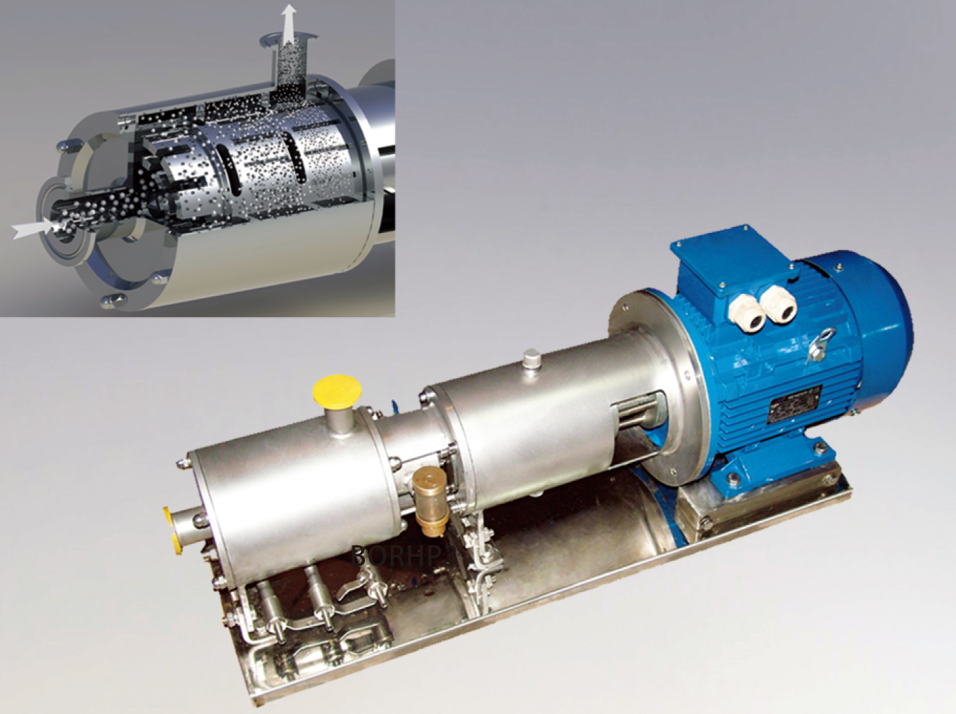
Material Engineering and Configurable Options
Industrial procurement demands high levels of equipment customization to ensure compatibility with aggressive chemical formulations, strict sanitation mandates, and explosive atmosphere classifications. Three-stage inline high shear mixers feature highly modular architectures that allow system engineers to specify exact material pairings across several mechanical subsystems:
• Chamber and Metallurgy Materials: The standard wetted parts are manufactured from high-grade austenitic stainless steel. Operators can select grade 304 stainless steel for non-corrosive industrial liquids or low-carbon grade 316L stainless steel for food-grade, cosmetics, and biopharmaceutical applications where chemical resistance and corrosion prevention are paramount.
• Elastomers and Static Seals: To prevent external leakage and survive chemical flush cycles, static seals are specified based on chemical compatibility. Options include Ethylene Propylene Diene Monomer for standard hot water and steam environments, Silicone for generic pharmaceutical fluids, or Fluororubber for aggressive chemical solvents, hydrocarbons, and high-temperature oils.
• Mechanical Shaft Sealing: The dynamic shaft seal separating the process chamber from the drive motor represents a critical configuration point. Single mechanical seals suffice for non-hazardous, self-lubricating fluids. However, double mechanical seals are mandatory for toxic, abrasive, or volatile materials. The double seal arrangement allows for an external barrier fluid flush system to cool the seal faces and contain any microscopic process migration. Seal face material pairings include carbon-to-silicon carbide, carbon-to-tungsten carbide, or tungsten carbide-to-tungsten carbide for highly abrasive slurry processing.
• Process Pipe Connections: For seamless system integration, the inlet and outlet ports can be machined with quick-connect tri-clamp fittings, SMS union threads, DIN union couplings, or heavy-duty industrial flanges to match pre-existing plant piping.
• Electrical Motors and Surface Finishes: Drive motors are available in standard enclosed configurations or explosion-proof variations certified for hazardous areas containing flammable vapors. Motor voltage and frequency profiles can be wound to 380V at 50Hz or 380V at 60Hz to match international factory grids. Finally, wetted surfaces can be customized with an industrial sandblasted finish or a highly reflective mirror-polished finish to prevent bacterial adhesion and streamline manual cleaning operations.
System Selection Metrics and Operational Integration
The primary operational matrix relies on aligning the targeted volumetric flow rate with the physical dimensions of the inlet and outlet process lines. Standard commercial line-up parameters are defined across a spectrum of industrial scale capacities.
For pilot plants or small-scale production lines, units operating with a flow rate of 5 to 7 cubic meters per hour utilize a motor rating between 4 and 7.5 kilowatts. These small-capacity configurations feature a DN40 inlet paired with a DN32 outlet to maintain optimal internal chamber velocity, operating with an exit pressure threshold between 0.15 and 0.20 Megapascals.
As production scales up to intermediate capacities of 12, 20, or 30 cubic meters per hour, the power requirements rise to 15, 22, and 37 kilowatts, respectively. These intermediate systems require a larger piping footprint, scaling from DN50 to DN65 on the inlet, with corresponding outlet dimensions of DN40 to DN50, generating active discharge pressures up to 0.50 Megapascals.
At the highest tier of continuous manufacturing, high-throughput pumps handle flow volumes of 40, 60, and 100 cubic meters per hour. These large-scale systems demand electric motors rated at 45, 75, and 110 kilowatts to rotate the heavy multi-stage rotor assemblies against fluid resistance. The process connections for these heavy-duty units expand to DN80, DN100, and DN125 on the inlet side, and DN65, DN80, and DN100 on the outlet side. They deliver significant fluid energy, generating output pressures from 0.50 up to 0.60 Megapascals while maintaining a stable shaft rotation velocity of 2900 revolutions per minute.

Description
In advanced process engineering, achieving ultra-fine particle dispersion and stable emulsions for highly viscous or high-solid materials requires multi-stage processing equipment. While single-stage systems excel in high-volume, single-pass processing, precision processing lines rely on the three-stage in-line high shear mixer, or multi-stage emulsification pump. This continuous inline equipment utilizes a multi-layered design to narrow particle size distribution, delivering high homogeneity in a single pass. This technical guide outlines the mechanical framework, design options, and engineering integration factors that govern this high-performance fluid control component.
Core Mechanics and Working Principles
The operational framework of a three-stage in-line high shear mixer is driven by a precision-engineered internal chamber containing three sets of nested, interlocking rotor and stator assemblies arranged in a serial axial configuration. When the system is energized, the common drive shaft rotates the three independent rotor heads at linear speeds of twenty to forty meters per second, driven by a high-velocity motor running at two thousand nine hundred revolutions per minute. This high-speed rotation generates a strong axial suction pressure at the central fluid inlet, acting as a self-priming force that draws unmixed, multi-phase materials directly into the primary mixing zone.
As fluid enters the tightly confined internal chamber, it is forced to travel through three sequential stages of hydraulic shear, localized cavitation, and intense turbulent flow. Each stage features progressively tighter tolerances and finer slot or perforation geometries on the stator rings. In the first stage, coarse materials and large solid agglomerates are shattered by basic mechanical impact and initial layer friction. The material is immediately forced into the second stage, experiencing higher pressure pulsations and increased shear frequency to break down intermediate droplets. Finally, the fluid enters the third stage, encountering maximum hydraulic resistance and fine micro-slots that eliminate any remaining particle non-uniformity. Because the wetted pathway consists of three successive shear zones, one hundred percent of the process fluid undergoes multiple cumulative dispersion cycles during a single pass, eliminating bypass channels or short-circuiting risks.
Core Performance Advantages and Operating Parameters
Integrating a three-stage inline emulsification pump into a continuous production line yields critical process advantages over traditional single-stage devices and legacy batch tank mixing networks. The primary technical advantage is the massive cumulative mechanical shear force generated within a single pass, which significantly narrows the particle and droplet size distribution profile. By reducing the reliance on long process loops and multiple tank-to-tank transfers, this multi-stage system allows processing plants to obtain stable emulsions and highly uniform dispersions in less time, maximizing throughput efficiency.
Furthermore, the three-stage nested architecture offers superior performance when processing high-viscosity formulations, high-solid concentrations, or difficult-to-dissolve compounds. The balanced distribution of radial forces across three dynamic zones ensures that the mixing pump operates with minimal vibration and low structural noise, protecting internal components from mechanical fatigue. This structural balance reduces physical wear on internal bearings and double mechanical seals, extending maintenance intervals. From an energy efficiency standpoint, applying concentrated, sequential shear forces directly onto a confined fluid stream allows manufacturers to optimize total power consumption, converting electrical energy into precise kinetic dispersion forces without generating excess heat in the product line.
Material Engineering and Configurable Options
Industrial procurement demands high levels of equipment customization to ensure compatibility with aggressive chemical formulations, strict sanitation mandates, and explosive atmosphere classifications. Three-stage inline high shear mixers feature highly modular architectures that allow system engineers to specify exact material pairings across several mechanical subsystems:
• Chamber and Metallurgy Materials: The standard wetted parts are manufactured from high-grade austenitic stainless steel. Operators can select grade 304 stainless steel for non-corrosive industrial liquids or low-carbon grade 316L stainless steel for food-grade, cosmetics, and biopharmaceutical applications where chemical resistance and corrosion prevention are paramount.
• Elastomers and Static Seals: To prevent external leakage and survive chemical flush cycles, static seals are specified based on chemical compatibility. Options include Ethylene Propylene Diene Monomer for standard hot water and steam environments, Silicone for generic pharmaceutical fluids, or Fluororubber for aggressive chemical solvents, hydrocarbons, and high-temperature oils.
• Mechanical Shaft Sealing: The dynamic shaft seal separating the process chamber from the drive motor represents a critical configuration point. Single mechanical seals suffice for non-hazardous, self-lubricating fluids. However, double mechanical seals are mandatory for toxic, abrasive, or volatile materials. The double seal arrangement allows for an external barrier fluid flush system to cool the seal faces and contain any microscopic process migration. Seal face material pairings include carbon-to-silicon carbide, carbon-to-tungsten carbide, or tungsten carbide-to-tungsten carbide for highly abrasive slurry processing.
• Process Pipe Connections: For seamless system integration, the inlet and outlet ports can be machined with quick-connect tri-clamp fittings, SMS union threads, DIN union couplings, or heavy-duty industrial flanges to match pre-existing plant piping.
• Electrical Motors and Surface Finishes: Drive motors are available in standard enclosed configurations or explosion-proof variations certified for hazardous areas containing flammable vapors. Motor voltage and frequency profiles can be wound to 380V at 50Hz or 380V at 60Hz to match international factory grids. Finally, wetted surfaces can be customized with an industrial sandblasted finish or a highly reflective mirror-polished finish to prevent bacterial adhesion and streamline manual cleaning operations.
System Selection Metrics and Operational Integration
The primary operational matrix relies on aligning the targeted volumetric flow rate with the physical dimensions of the inlet and outlet process lines. Standard commercial line-up parameters are defined across a spectrum of industrial scale capacities.
For pilot plants or small-scale production lines, units operating with a flow rate of 5 to 7 cubic meters per hour utilize a motor rating between 4 and 7.5 kilowatts. These small-capacity configurations feature a DN40 inlet paired with a DN32 outlet to maintain optimal internal chamber velocity, operating with an exit pressure threshold between 0.15 and 0.20 Megapascals.
As production scales up to intermediate capacities of 12, 20, or 30 cubic meters per hour, the power requirements rise to 15, 22, and 37 kilowatts, respectively. These intermediate systems require a larger piping footprint, scaling from DN50 to DN65 on the inlet, with corresponding outlet dimensions of DN40 to DN50, generating active discharge pressures up to 0.50 Megapascals.
At the highest tier of continuous manufacturing, high-throughput pumps handle flow volumes of 40, 60, and 100 cubic meters per hour. These large-scale systems demand electric motors rated at 45, 75, and 110 kilowatts to rotate the heavy multi-stage rotor assemblies against fluid resistance. The process connections for these heavy-duty units expand to DN80, DN100, and DN125 on the inlet side, and DN65, DN80, and DN100 on the outlet side. They deliver significant fluid energy, generating output pressures from 0.50 up to 0.60 Megapascals while maintaining a stable shaft rotation velocity of 2900 revolutions per minute.
Application


Specifications
Advantage Comparison


GET IN TOUCH NOW


