


The number of discharge ports is a critical structural parameter defining how the multiphase gas-liquid mixture is expelled from a bottom-mounted aerator into the surrounding broth. While easily overlooked as a simple component count, this parameter directly influences the fluid dynamics, localized pressure drops, and jet velocity profiles dictated by the aerator's internal impeller, stator, and distributor assembly.
In aerobic fermentation systems, the bottom-mounted aerator acts as the heart of oxygen transfer. It induces gas, shears it into micro-bubbles, and forces it radially into the tank. The discharge ports serve as the final nozzle-like transitions where this high-energy mixture enters the fermentation broth.
The BOAO DAWT series utilizes different discharge port counts—ranging from 8 to 16—across its model matrix. Understanding the engineering logic behind these variations allows project engineers to correctly interpret technical specifications and optimize vessel geometry matching without assuming that a higher port count automatically equals better aeration performance.
Defining the Discharge Port Parameter
The number of discharge ports specifies the total count of machined fluid passages distributed around the perimeter of the aerator's stator or distributor housing.
Operationally, after ambient air is drawn down the intake pipe and sheared into micro-bubbles (roughly 100 microns) by the star-shaped impeller, the fluid accumulates kinetic energy. This pressurized gas-liquid mixture is then divided and projected out through these designated ports.
It is important to classify this parameter as a geometric specification rather than a direct performance metric. While a specific port count describes the structural division of the fluid, it cannot independently quantify volumetric air intake (Nm³/h) or standard oxygen transfer rates (OTR) without factoring in individual port cross-sections, total open area, and impeller tip speed.
Hydrodynamic Functions of Ports in Fermentation Vessels
Rather than being mere openings, discharge ports function as hydraulic nozzles that dictate the initial flow pattern at the base of the fermenter. In bottom-mounted designs, their placement and count serve three main engineering purposes:
- Establishing Kinetic Jet Velocity: For a given volumetric flow rate, the number of ports—combined with their individual cross-sectional areas—determines the exit velocity of the fluid. This velocity must be high enough to project the bubbles across the entire radius of the tank floor, yet controlled enough to avoid excessive localized shear stress.
- Preventing Bottom Sedimentation: The horizontal or radial arrangement of these ports ensures a sweep-feed flow pattern along the vessel floor. This eliminates flow stagnation zones beneath the impeller, keeping heavy substrates or dense cell cultures in continuous suspension.
- Initial Bubble Distribution: By splitting the primary fluid stream into multiple secondary jets, the ports initiate the macro-mixing process, helping the micro-bubbles distribute evenly across the tank diameter before buoyancy drives them upward.
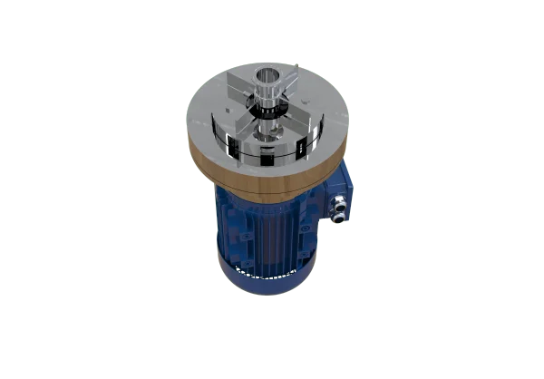
Engineering Logic Behind the DAWT Series Port Scaling
The technical specifications of the DAWT series reveal a deliberate scaling of discharge ports corresponding to machine size, volumetric throughput, and motor power ratings:
- Pilot & Small Scale (DAWT7.5 to DAWT22): Configured with 8 discharge ports.
- Medium Industrial (DAWT40 & DAWT55): Configured with 12 discharge ports.
- Large Industrial (DAWT75 to DAWT185): Configured with 16 discharge ports.
- This progression aligns directly with the fluid handling capacity of the machines. As motor power grows from 0.75 kW to 18.5 kW, the air intake scales up significantly from 11 Nm³/h to 330 Nm³/h.
- If a massive unit like the DAWT185 were restricted to only 8 ports, the localized fluid velocity at each port would be excessively high, causing extreme mechanical shear that could lyse sensitive biological cells. Conversely, splitting the high volumetric flow of a large machine across 16 ports expands the total discharge area. This maintains an optimal balance between high volumetric circulation and gentle, widespread fluid distribution across large-diameter (30 to 50-ton) tank floors.
Deconstructing Selection Misconceptions: Is More Always Better?
A common misconception in equipment procurement is that a higher discharge port count automatically yields superior aeration or more uniform mixing. In fluid machinery design, port count must always be optimized alongside individual port geometry and total volumetric throughput.
An arbitrary increase in the number of ports without a corresponding increase in impeller pumping capacity will backfire. It reduces the backpressure within the stator chamber, causing the exit jet velocity to drop. Instead of projecting a powerful radial loop to sweep the tank walls, the gas-liquid mixture will merely seep out of the ports and float straight up along the aerator shaft, creating a massive mixing dead zone at the tank perimeter.
Therefore, the discrete steps of 8, 12, and 16 ports in the DAWT series represent optimized balance points calibrated to the specific impeller sizes and standard operating RPMs (2900/1450 RPM) of those model groups.
Supporting Effective Technical Communication
Maintaining a clearly defined port count allows equipment manufacturers, process engineers, and procurement teams to align on exact structural features. Crucially, this metric prevents costly confusion during the drafting of piping and instrumentation diagrams (P&IDs).
Specifically, it prevents engineers from conflating the air inlet (the primary intake channel admitting atmospheric air into the top of the unit) with the discharge openings (the multiple downstream ports where the multi-phase fluid exits the distribution structure). Because these components handle entirely different fluid phases and operational pressures, they are non-interchangeable on a datasheet.
How to Interpret This Parameter in a Technical Datasheet
When auditing technical datasheets for project specifications, engineers should evaluate the discharge port count through a systematic framework:
Cross-Verify Manufacturer Terminology
Begin by confirming the manufacturer's exact definition of a discharge port. This is essential when benchmark-comparing products across vendors, as internal distributor geometries and proprietary structural naming conventions vary across the market.
Map Geometry via Engineering Drawings
Utilize the numerical port count as a starting reference point, but always cross-reference it with certified equipment drawings. The raw number indicates the count of openings but cannot reconstruct the physical layout, individual nozzle diameters, or inclination angles—all of which are critical for precise computational fluid dynamics (CFD) modeling.
Look Beyond Component Counts for Empirical Validation
Avoid using the port count as a shortcut to estimate mass transfer efficiency. If a specific process requires guaranteed fluid velocity profiles or strict dissolved oxygen (DO) homogeneity, engineers should bypass geometric assumptions and request empirical test data, factory acceptance test (FAT) records, or certified oxygenation capacity (kg O₂/h) logs.
For the DAWT series, while the published port counts accurately catalog the physical differences between the small, medium, and large model groups, they represent just one piece of the broader fluid dynamics puzzle. Fully calculating the total discharge area or predicting exact oxygen transfer rates requires pairing the port count with broader design parameters like operational RPM and impeller geometry.
Why This Structural Parameter Matters
Ultimately, the number of discharge ports serves as an invaluable reference point for identifying model configurations and sizing internal distribution mechanics. Its true significance lies in structural classification rather than standalone performance predictions. The actual behavior of the discharged gas-liquid plume is dictated by the complete distributor design, the rheology of the fermentation broth, and active operating conditions.
By treating the discharge port count as a specific, integrated geometric parameter rather than an isolated metric, engineers can read technical datasheets with greater accuracy, distinguish verified structural specifications from performance assumptions, and make data-driven decisions during facility design and equipment selection.


